

Introduction to Fiber Optic Converters
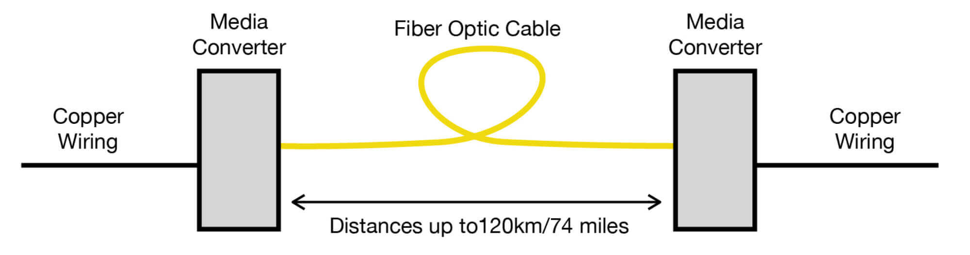
Fiber Optic Converters (also known as Media Converters) are devices that convert the electrical signal used in copper wiring such as Ethernet or Serial Data into light waves for transmission over fiber optic cable. They are commonly used in pairs, one at each end of the fiber cable span, enabling two devices or networks with copper wiring to be connected over fiber optic cable.
Benefits of Fiber optics
Fiber optics are an efficient, reliable, low-energy way to transmit copper-based signals over long distances while providing immunity to electrically noisy environments. Many modern networks utilize fiber optic cable between two copper-based distribution points – for example between two floors in a multi-story building. Using Fiber Optic Converters, you can connect two devices that require copper signaling by utilizing the fiber optic cable connecting the two floors together.
This guide serves as an overview to those who are new to Fiber Optic Converters and fiber optics, and presents general information about copper-to-fiber converters, their components, and general features.
Please note that while there are many types of Fiber Optic Converters, for the purposes of this guide we will be discussing stand-alone, point-to-point single-service systems.
Types of Signals
The most popular signal type supported by Fiber Optic Converters is Ethernet. An Ethernet Fiber Optic Converter accepts the copper Ethernet signals, converts it to light for transmission over fiber optic cable, and then converts the light back into a copper electrical signal at the other end of the fiber span, providing a seamless Ethernet connection over fiber cable. This type of converter is popular as Ethernet is everywhere these days and a fiber converter is useful in extending an Ethernet network’s reach, such as in a large campus networks or providing remote connections to ethernet devices in industrial applications.
While Ethernet is the most popular, it is not the only type of Fiber Optic Converter available. There are many different Fiber Optic Converters designed to transmit various signals over fiber optic cable.
No matter which signal is transported, it’s important to remember that the job of the fiber converter is to be the device that translates the electrical copper signals into light for transmission over fiber optic cable. So at their core, all fiber converters generally work the same way.
Construction/Mounting Options
Stand-alone fiber converters have various mounting options depending on their physical characteristics and powering requirements. These mounting options include:
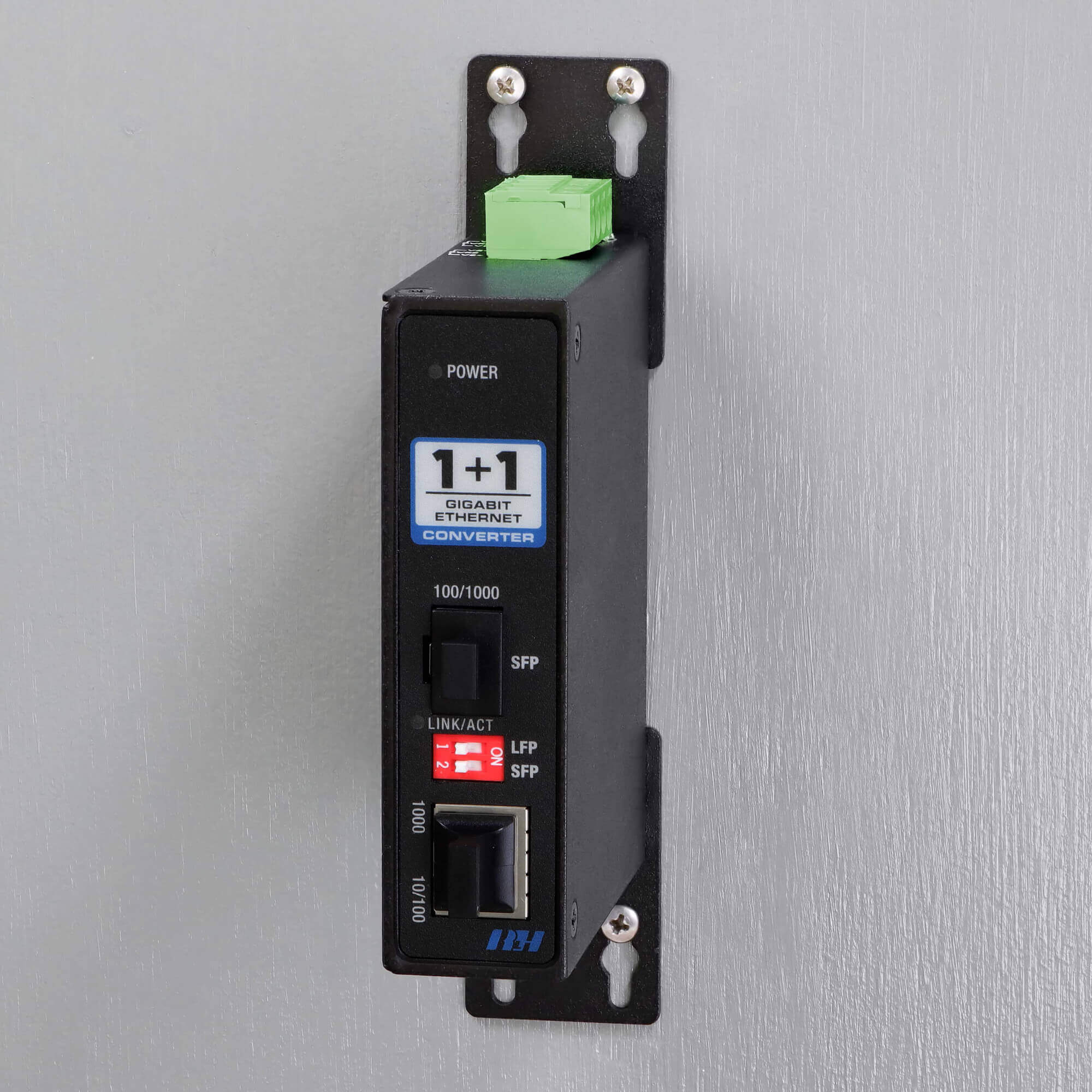
Wall Mounting:
Devices intended for commercial or industrial use may be provided with mounting ears for wall or panel attachment. This type of mounting is common in telecommunication rooms. Typically, the wall mounting surface is a plywood backboard, and the mounting ears are configured on the housing so that it may be fastened to the surface with screws.
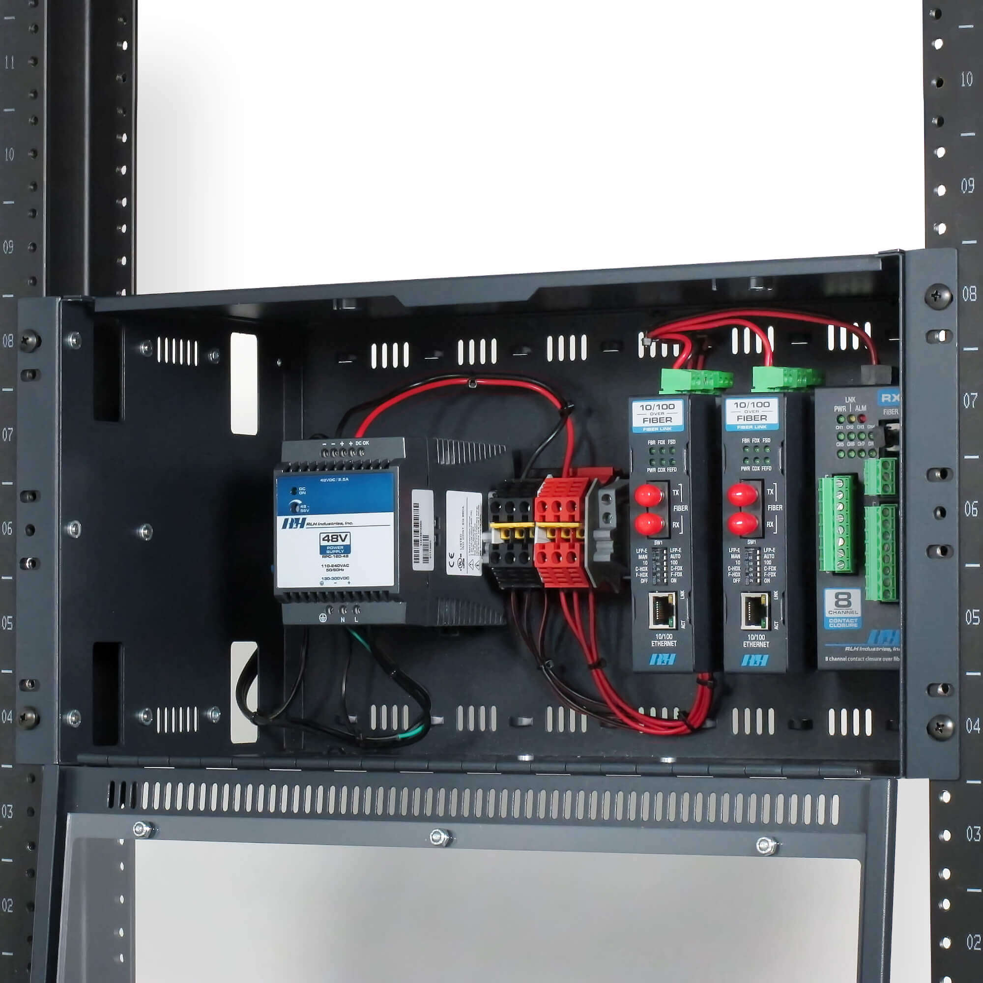
Rack Mounting:
Fiber Optic Converters are commonly found in standard EIA 19” or 23” equipment racks alongside servers, network switches, and other network devices. The typical fiber converter will require a rack mount bracket or rack mount shelf that is sold separately. These accessories will mount into the rack and then hold or house the Fiber Optic Converter.
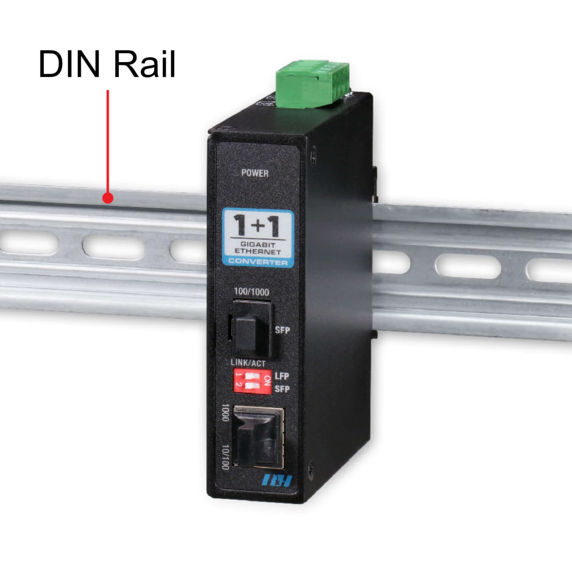
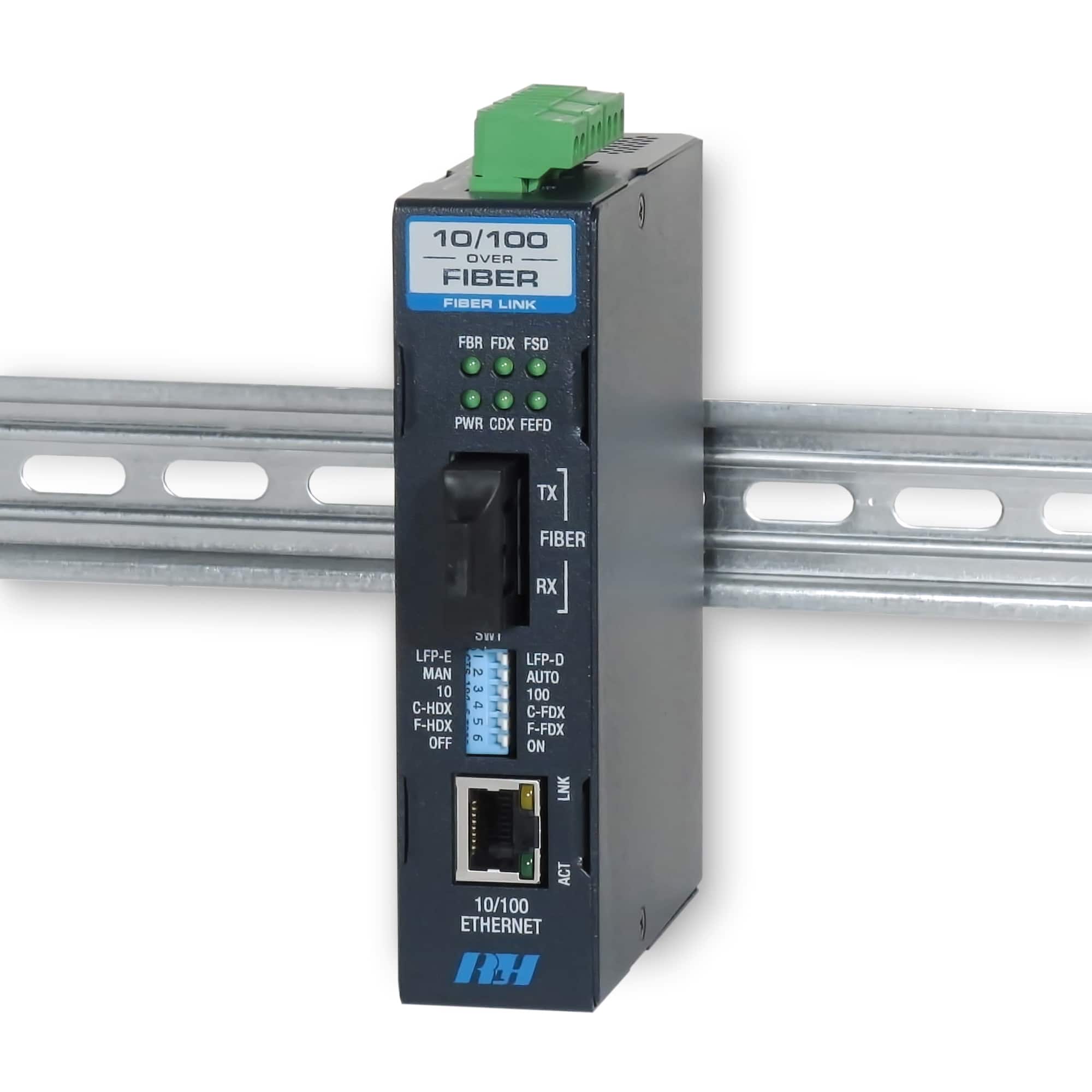
DIN Rail Mounting:
Fiber optic converters used in commercial and industrial environments are commonly intended for DIN rail mounting and have clips for easy attachment to the rail. T-35 DIN rails are metal brackets designed for securely attaching electrical and industrial control products such as circuit breakers, terminal blocks, power supplies, actuators, solenoids, and other industrial control equipment. DIN rail mounting is commonly used in Automation and Control applications and the rail may be attached to a wall, panel, or backboard.
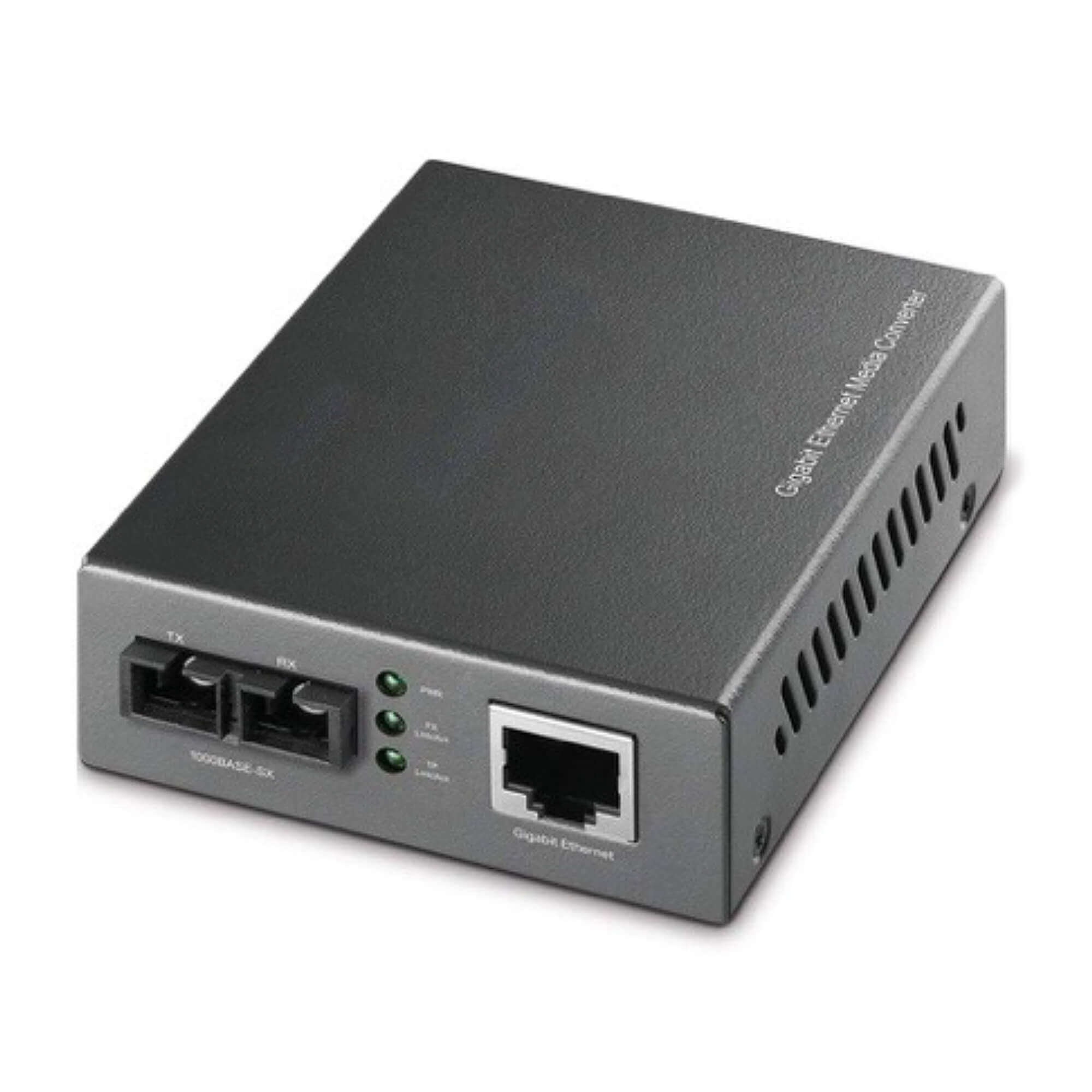
Desktop Use:
Desktop Style fiber optic converters are meant to be simply placed on a flat surface such as a table or equipment shelf. These may be secured in place with cable ties or hook and loop fasteners. This is commonly the case with retail or home applications where commercial mounting styles aren’t practical or necessary.
Power Connectors
All Fiber Optic Converters require power to operate. There are two different types of power connectors commonly used:
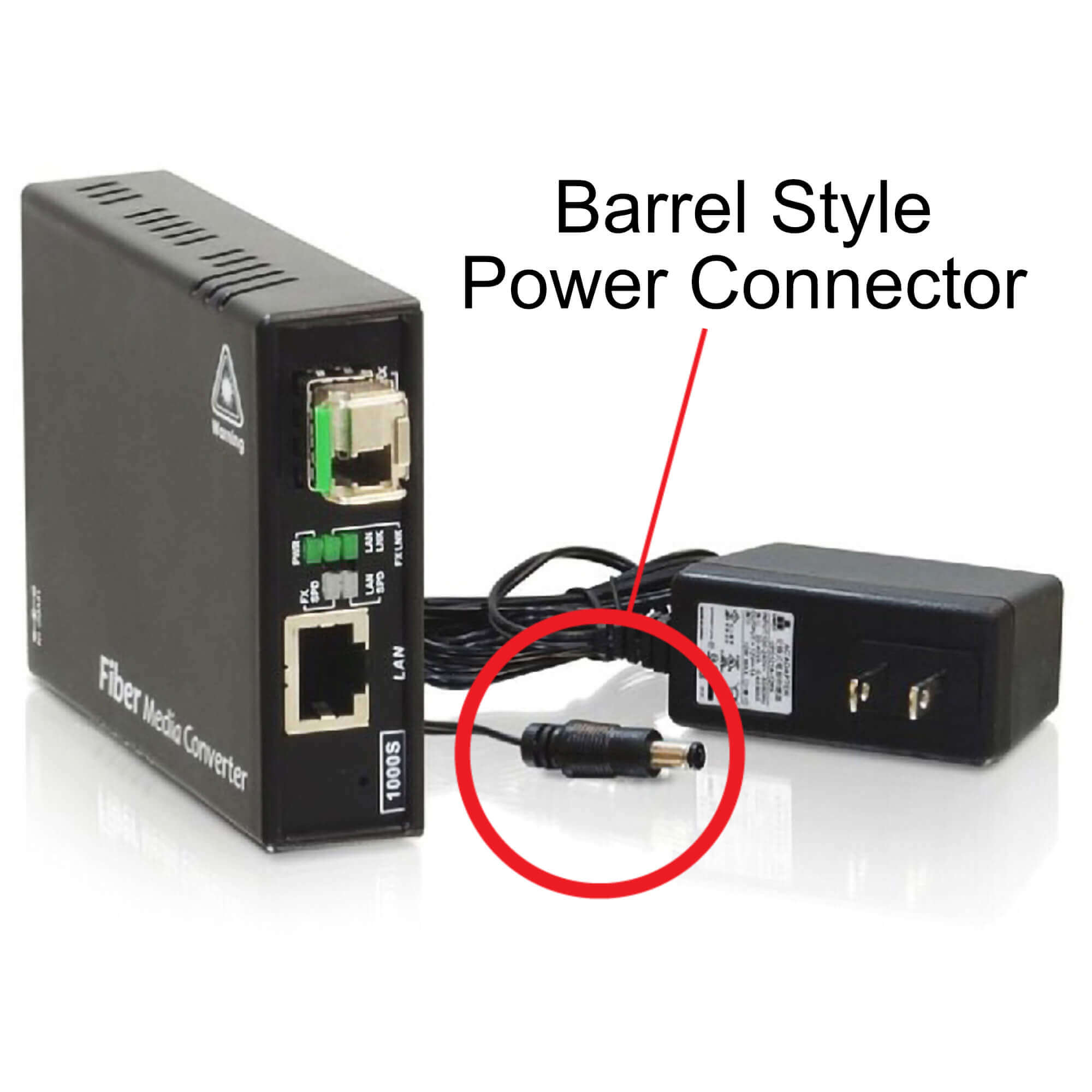
Barrel Connectors:
Barrel connectors are typically used when the power supply is included with the fiber converter.
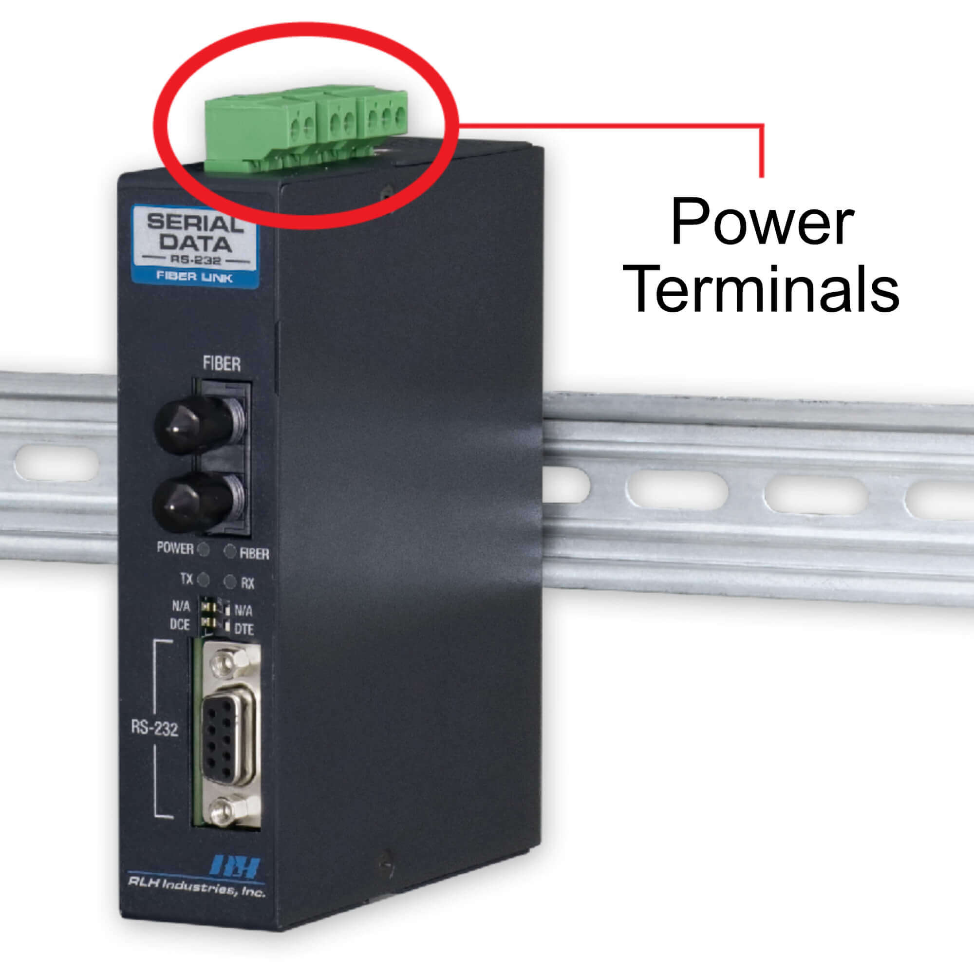
Power Terminals:
Power terminals are typically screw down terminals that connect wiring to a separate power source and are the most popular powering method. Industrial Fiber Converters typically do not include a power supply due to the added cost of an industrial grade power supply, and the likelihood that one may already be present at the installation site.
Operating Temperature
All Fiber Optic Converters have a rated operating temperature. Typically, the wider the operating temperature range, the higher the cost will be. Fiber optic converters with a wide operating temperature will use specialized, higher-cost components to ensure reliable operation at more extreme temperatures. This typically results in a higher unit price along with the expectation of more reliable performance.
Alarming
Some Fiber Optic Converters will have built-in alarm capabilities. Typically, Fiber Optic Converters will offer a status indicator that indicates the overall health and activity of the system. Higher end Fiber Optic Converters may include an additional, Integrated Relay Alarm which may be used to trigger an alert if the system malfunctions or is powered off.
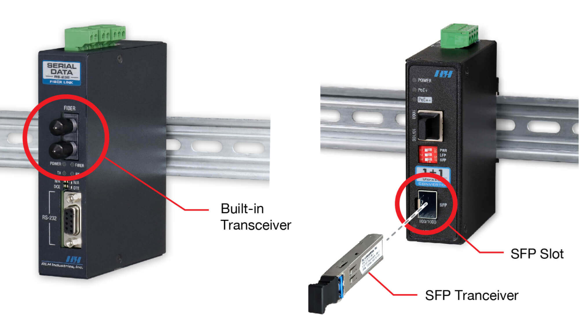
Fiber Transceivers
Fiber transceivers are the most complex part of the Fiber Optic Converter. They are either built-in and permanently affixed to a Fiber Optic Converter or they may be pluggable. When pluggable, they’re referred to as small form-factor pluggable (SFP). Fiber Optic Converters that support SFPs will have an SFP slot that’s empty, and the end user is expected to purchase an SFP separately.
Fiber transceivers are the component that emits the light signal into the fiber cable. The following factors are the most important aspects of a fiber transceiver and should be taken into consideration when selecting a fiber converter with a built-in transceiver or an SFP Transceiver for use with a fiber converter with an SFP slot.
Connector Styles
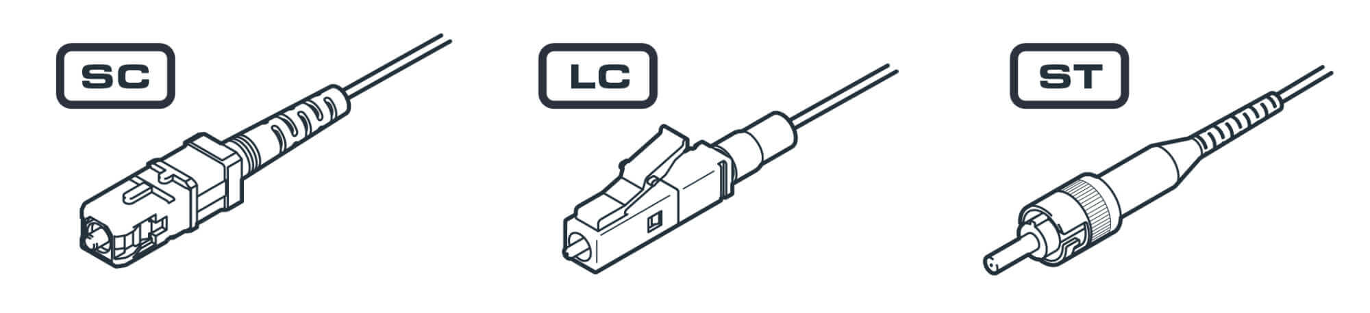
The fiber connector is at the end of the fiber cable that plugs into a Fiber Optic Converter and makes the link between the fiber cable and the Fiber Optic Converter.
There are 3 common fiber connectors that a Fiber Optic Converter’s fiber transceiver are designed to support. SC, LC, and ST are the most common and are illustrated here.
When shopping for fiber converters a manufacturer may offer different options for the same fiber converter, each specifying a different fiber transceiver. These different fiber transceivers are necessary to support the various common fiber connector types.
The example below is part of a fiber converter ordering list. This fiber converter utilizes a built-in fiber transceiver, and the manufacturer offers two connector-ordering options.
|
Mode |
Connector |
Distance |
Fibers |
Wavelength |
Part Number |
|
|---|---|---|---|---|---|---|
|
Option 1 |
Multimode |
SC |
2km/1.2 miles |
Dual Fiber |
1310nm |
EFD-03-2 |
|
Option 2 |
Multimode |
ST |
2km/1.2 miles |
Dual Fiber |
1310nm |
EFD-04-2 |
Fiber Modes
Fiber optic transceivers and fiber cable have a construction characteristic called a “Mode”. There are two primary Modes, Singlemode and Multimode. A fiber transceiver will be specifically designed to be used with either Singlemode Fiber or Multimode Fiber.
These modes indicate the diameter of the optical glass within each strand of fiber, which affects how the fiber transceiver must operate to successfully emit light through the various diameters of optical glass within a fiber cable.
When selecting a fiber converter that uses either built-in or an SFP transceiver, it is important to confirm that the transceiver mode type matches the mode type of your fiber cable for the system to operate correctly.
|
Singlemode Fiber |
Multimode Fiber |
|---|---|
|
Has a smaller optical core than multimode fiber cable |
Has a larger optical core than Singlemode |
|
Fiber transceivers are typically more expensive |
Fiber transceivers are typically less expensive |
|
Fiber cable is less expensive |
Fiber cable is more expensive |
Single and Dual Fiber Transceivers
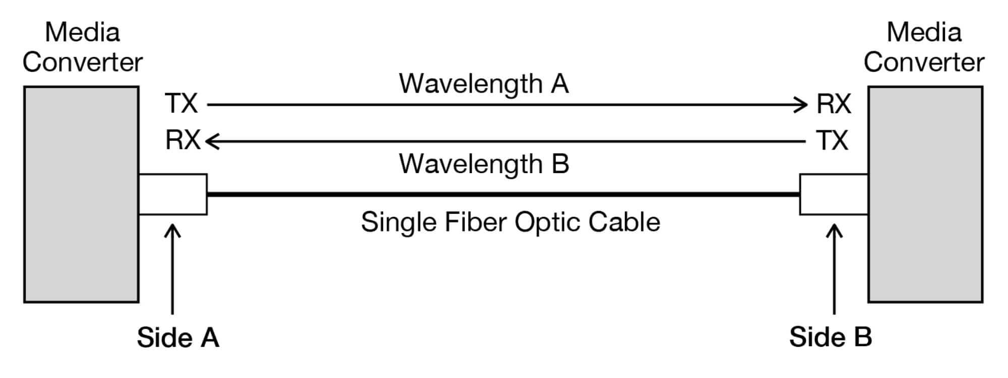
Single Fiber Transceivers
In scenarios where minimizing the use of fiber strands is necessary, single fiber transceivers are available. These transceivers are typically more expensive as they’re designed to transmit and receive a light signal over a single fiber strand. With these types of transceivers each side transmits and receives light on a different wavelength to avoid interference within the fiber cable. These single fiber transceivers (also known as bi-directional transceivers) must be matched to each other, with one side using a Side A transceiver and the matching transceiver using a Side B. In the Example above, the Side A transceiver will transmit light at Wavelength A, and the Side B transceiver will transmit light at Wavelength B.
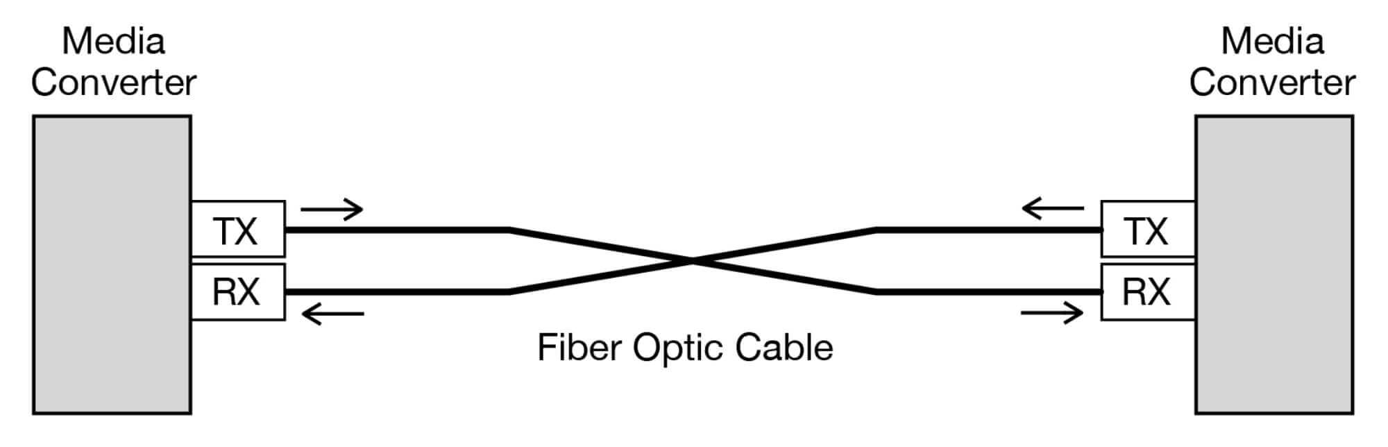
Dual Fiber Transceivers
Transceivers may use separate fibers for transmit (TX) and receive (RX) signals, so that a pair of fibers is required for a complete system. Since these dual fiber TX and RX signals use separate fibers, they can use the same wavelength without interference on each side of the fiber span. This simplifies the selection of transceiver optics as you can use the same transceiver on both sides and simply ensure the transmit fiber on one end of the system plugs into the receive port on the other end.
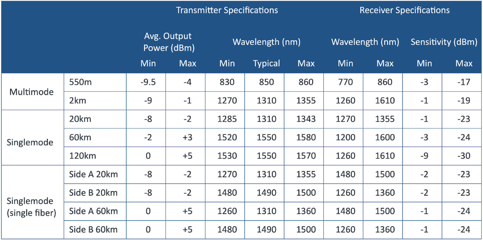
Distance – Optical Power & Receiver Sensitivity
The distance rating for a fiber transceiver is determined by its transmitter’s optical power and its receiver’s sensitivity. This is the same whether the fiber optic converter uses an SFP transceiver or has a built-in, affixed transceiver as part of its design.
Transceivers will typically list the transmitter power (TX Power) and the receiver sensitivity (RX Sensitivity) range in dBm. These are the two most important attributes that indicate the useable range of the signals.
The transmitter Output Power is the intensity of the light being sent through the fiber. The Receiver Sensitivity is the amount of that light required for the signal to be received at the other end of the fiber span.
To keep this characteristic relatively simple, most manufacturers provide a distance specification along with the optical power and receiver sensitivity values. The distance ranges are generally reliable and safe to follow as the manufacture has typically calculated the distance rating using the optical power output and receiver sensitivity following the EIA/TIA 568 standard for fiber optic cables.
Different Classes of Fiber Optic Converters
After looking at all the different characteristics of fiber optic converters, we can place converters into different classes based on capabilities, features, and construction. A fiber converter will typically fall into one of these categories, listed from lowest to highest cost.
Retail
The housing style and operational performance for retail or home use typically doesn’t require the robust operation or build strength of commercial units as cost is a major consideration in retail applications, and industrial ruggedness isn’t typically required. These units may have lightweight plastic housings that are intended for home or desktop use in environmentally-controlled locations.
|
Price: |
Low Cost |
|
Signal Types Supported: |
Ethernet |
|
Mounting Options: |
Desktp Style |
|
Power Connectors: |
Barrel Connectors |
|
Power Supply Included: |
Almost Always |
|
Fiber Transceivers Supported: |
SFP or Affixed |
|
Fiber Modes Supported: |
Singlemode or Multimode |
|
Single or Dual Fiber Supported: |
Yes |
|
Operating Temperature: |
0~40°C or 0~50°C |
|
Alarming: |
LED Indicators |
Commercial
Commercial-grade converters will have robust operational criteria for demanding use in server rooms, equipment rooms, or other environmentally-controlled areas. These systems may have accommodations for rack or DIN rail mounting and may require commercial-style power supplies as well.
|
Price: |
Mid-Tier Pricing |
|
Signal Types Supported: |
Ethernet & Common Serial Data Protocols |
|
Mounting Options: |
Wall & Desktop Style |
|
Power Connectors: |
Power Terminals |
|
Power Supply Included: |
Sometimes |
|
Fiber Transceivers Supported: |
SFP or Affixed |
|
Fiber Modes Supported: |
Singlemode or Multimode |
|
Single or Dual Fiber Supported: |
Yes |
|
Operating Temperature: |
0~50°C |
|
Alarming: |
LED Indicators; Sometimes Relay Alarms |
Industrial
Industrial Fiber Optic Converters are the most robust. They typically come with rugged, metal housings and environmentally-hardened electronics for critical infrastructure applications or use where an extended operating temperature range is required. These units are powered by separate industrial power supplies and are primarily DIN rail or wall mounted.
|
Price: |
Highest |
|
Signal Types Supported: |
Ethernet, Serial Data Protocols, DS0/DS1, Specialty Automation & Control Signals |
|
Mounting Options: |
DIN Mount |
|
Power Connectors: |
Redundant Power Terminals |
|
Power Supply Included: |
No; Sold Separately |
|
Fiber Transceivers Supported: |
SFP or Affixed |
|
Fiber Modes Supported: |
Singlemode or Multimode |
|
Single or Dual Fiber Supported: |
Yes |
|
Operating Temperature: |
-20~60°C or -40~70°C |
|
Alarming: |
LED Indicators & Relay Alarms |
In Conclusion
We hope you enjoyed learning about fiber optic converters as much as we enjoy designing and manufacturing them! We’ll be sure to update this guide as the industry evolves and new technologies and standards become common place. If you’re interested in learning more about fiber optics, you might want to check out Fiber Patch Panels: A Beginner’s Guide.
Learn More
- About Fiber Optics – The Fiber Optic Association: https://www.thefoa.org/
- About EIA Standards – Electronic Industries Alliance: https://www.ecianow.org/
- About IEC Standards – International Electrical Commissions: https://iectest.iec.ch/
- About TIA Standards – Telecommunications Industry Association: https://tiaonline.org/
- About ISO Standards – International Standards Organization: https://www.iso.org/